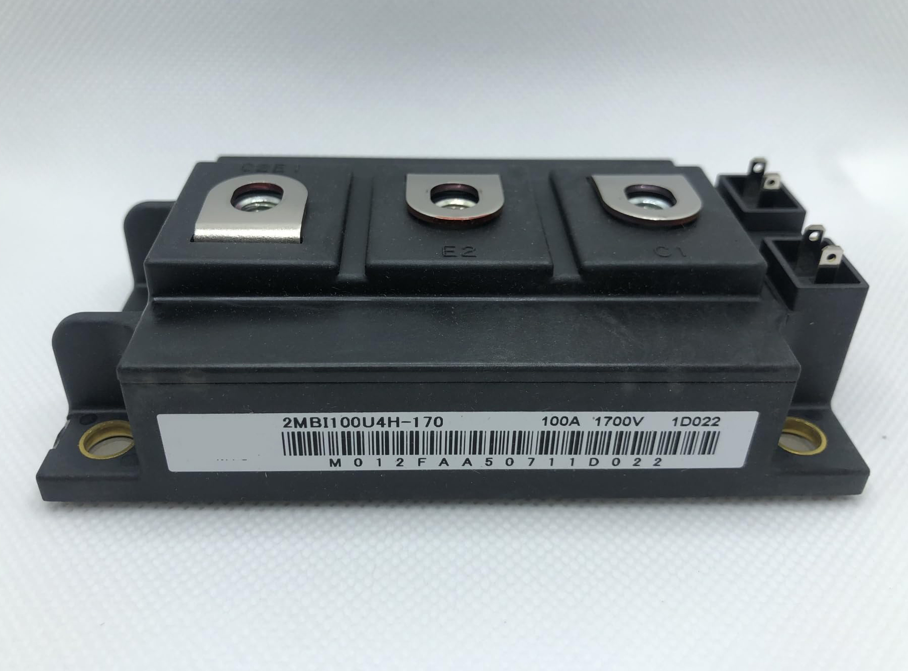
IGBT (Insulated Gate Bipolar Transistor) modules are the bedrock of modern power electronics, finding widespread application across critical sectors like industry, energy, and transportation. Today, we're taking an in-depth look at a high-performance IGBT module from Fuji Electric Device Technology Co., Ltd. – the 2MBI300U4H-170.

Core Features & Key Parameters Overview
The 2MBI300U4H-170 is an IGBT module specifically engineered for high-voltage and high-current applications. Its exceptional performance parameters ensure stable operation even in the most demanding environments. Here are some of its core technical highlights:
High Voltage Withstand Capability: Features a Collector-Emitter Voltage (VCES) of up to 1700V.
Robust Current Handling: Capable of a continuous Collector Current (IC) of 400A at TC=25°C and 300A at TC=80°C. Its Pulsed Collector Current (ICP) can reach 800A at TC=25°C.
Low Saturation Voltage Drop: With a typical Collector-Emitter Saturation Voltage (VCE(sat) chip) of 2.25V at Tj=25°C and IC=300A, it significantly reduces power loss and boosts efficiency.
Excellent Switching Characteristics: Boasts fast turn-on (ton) and turn-off (toff) times, ensuring highly efficient power conversion in high-frequency applications.
Strong Power Dissipation Capability: Offers a Collector Power Dissipation (PC) of up to 1470W per device.
These characteristics make the 2MBI300U4H-170 a reliable choice for inverters, converters, UPS systems, and other high-power density applications.
Module Structure & Equivalent Circuit
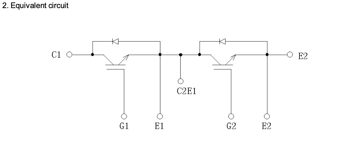
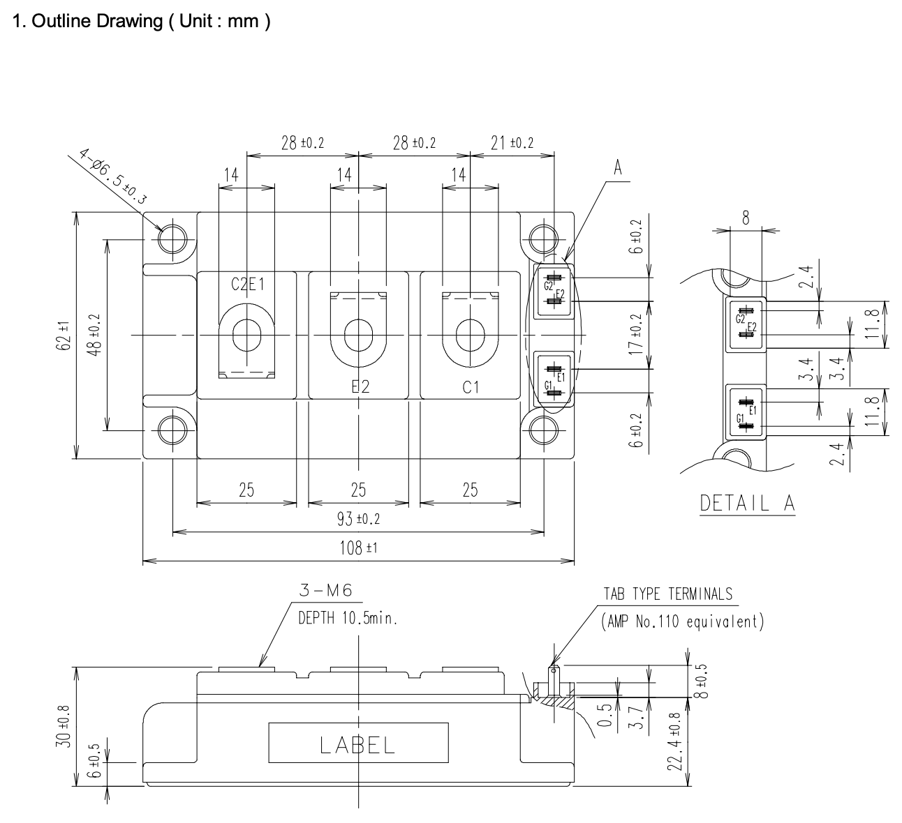
This module features a compact design, facilitating easy integration into various power electronic systems. Its datasheet provides detailed outline drawings and an internal equivalent circuit diagram. The equivalent circuit clearly illustrates the connection of the internal IGBTs and free-wheeling diodes, which is crucial for engineers during circuit design and simulation.

2MBI300U4H-170 Manufacturer
The 2MBI300U4H-170 is manufactured by Fuji Electric Device Technology Co., Ltd. A renowned name in power electronics and semiconductors, Fuji Electric's expertise and commitment to product quality are evident in the 2MBI300U4H-170, a key part of their extensive IGBT module lineup.
2MBI300U4H-170 Equivalent Circuit
The module's equivalent circuit typically features a dual-unit series configuration, often referred to as a Half-Bridge structure. This means it houses two main power switching units. Each unit consists of an IGBT (Insulated Gate Bipolar Transistor) and an anti-parallel Fast Recovery Diode (FWD). These two IGBT-FWD pairs are connected in series, with a central output terminal (e.g., connecting to the load) and ends connected to the positive and negative terminals of the DC Bus. This configuration significantly simplifies the power stage design for applications like inverters and converters by enabling control of both the upper and lower arms of the AC output within a single package.
2MBI300U4H-170 Dimension
The 2MBI300U4H-170 IGBT module is designed with a standard industrial footprint for easy integration. Its main body measures 108.0 mm in length by 62.0 mm in width, with an overall height of 30.0 mm. For secure mounting, it features four M5 screw holes, spaced 93.0 mm apart lengthwise and 50.0 mm apart widthwise.

Beyond its basic footprint, the module's outline drawing provides precise details for terminal placement and other structural features, crucial for proper mechanical design and heatsink integration. These specific dimensions ensure reliable physical fit and optimal thermal management within various power electronics systems.
2MBI300U4H-170 vs 2MBI400U4H-170 Comparison
In high-performance power electronics applications, the choice of IGBT modules is critical for system efficiency, reliability, and cost. Fuji Electric's 2MBI300U4H-170 and 2MBI400U4H-170 are two common 1700V-class modules from their U4H series. While they belong to the same series, they exhibit significant differences in current handling capability and thermal performance.
1. Parameter Comparison Table
| Parameter | 2MBI300U4H-170 | 2MBI400U4H-170 | Unit | Notes |
|---|
| VCES (Collector-Emitter Voltage) | 1700 | 1700 | V | Rated Voltage |
| Ic (Collector Current) | 300 (at Tc=80°C) | 400 (at Tc=80°C) | A | Continuous collector current |
| Icp (Pulsed Collector Current) | 800 (at Tc=25°C) | 800 (at Tc=25°C) | A | Peak pulsed current |
| Pc (Collector Power Dissipation) | 1470 (at Tc=25°C) | 1960 (at Tc=25°C) | W | Total power dissipation capability |
| VCE(sat) (Saturation Voltage) | 2.25 (Typ., Ic=300A, Tj=25°C) | 2.5 (Typ., Ic=400A, Tj=25°C) | V | Key parameter for conduction losses |
| | 2.65 (Typ., Ic=300A, Tj=150°C) | 2.9 (Typ., Ic=400A, Tj=150°C) | V | |
| VF (FWD Forward Voltage) | 2.05 (Typ., IF=300A, Tj=25°C) | 2.35 (Typ., IF=400A, Tj=25°C) | V | Key parameter for diode losses |
| | 1.8 (Typ., IF=300A, Tj=150°C) | 2.05 (Typ., IF=400A, Tj=150°C) | V | |
| Rth(j-c) IGBT (Thermal Resistance) | 0.085 (Max) | 0.064 (Max) | °C/W | Junction-to-case thermal resistance; lower is better for heat dissipation |
| Rth(j-c) FWD (Thermal Resistance) | 0.17 (Max) | 0.10 (Max) | °C/W | Junction-to-case thermal resistance; lower is better for heat dissipation |
| Package Type | U4H (Typically Half-Bridge Module) | U4H (Typically Half-Bridge Module) | N/A | Package dimensions and pinout are usually identical |
Note: The values above are typical (Typ.) or maximum (Max.). Please refer to the latest datasheet for precise figures.
2. Key Differences and Application Considerations
From the parameter comparison, the primary distinctions between the 2MBI300U4H-170 and 2MBI400U4H-170 lie in their current handling capability and thermal performance:
Rated Current: The most evident difference, reflected in the model names, is the rated continuous current. The 2MBI400U4H-170 can handle 400A continuous current at Tc=80°C, whereas the 2MBI300U4H-170 is rated for 300A. This means the 400U4H module is capable of driving higher power loads.
Power Dissipation Capability: The 400U4H module's total collector power dissipation capability (1960W) is significantly higher than that of the 300U4H (1470W), aligning with its increased current handling capacity.
Saturation and Forward Voltage Drop: At their respective rated currents, the IGBT saturation voltage VCE(sat) and FWD forward voltage VF for the 400U4H are slightly higher than those of the 300U4H. This is often due to the larger effective area required for higher current-rated chips, which might lead to a slight increase in voltage drop at their rated currents, though still within acceptable limits. In practical applications, precise calculations of losses based on the actual operating current and junction temperature are necessary.
Thermal Resistance: This is a critical parameter. Both the IGBT and FWD thermal resistances (Rth(j-c)) of the 2MBI400U4H-170 are notably lower than those of the 2MBI300U4H-170. Lower thermal resistance means the module can more efficiently transfer heat generated internally from the chip to the heatsink. This allows it to handle higher power under the same cooling conditions, or achieve lower junction temperatures for the same power, which is vital for long-term module reliability.
It's worth noting that despite the 400U4H's higher continuous current capability, both modules share the same pulsed collector current (Icp) of 800A at Tc=25°C. This might suggest similar transient overload capabilities over very short durations, but for sustained high-current output, the 400U4H offers a distinct advantage.
3. How to Choose?
The decision between the 2MBI300U4H-170 and 2MBI400U4H-170 primarily hinges on your specific application requirements:
Power Requirements: If your design necessitates driving greater power, such as higher-rated motor drives, solar inverters, or UPS systems, then the 2MBI400U4H-170 is the more straightforward choice due to its superior continuous current handling capability.
Cost vs. Headroom: Generally, modules with higher current ratings come at a higher cost. If the 2MBI300U4H-170 adequately meets your design's current requirements with sufficient safety margin, then opting for it might be more cost-effective. However, simply meeting the "rated" current isn't enough; always consider the system's actual load profile, instantaneous peaks, and cooling conditions.
Cooling Conditions: If your system has restricted cooling capabilities, or if you aim for the module to operate at lower junction temperatures for extended lifespan, the 2MBI400U4H-170's lower thermal resistance provides a significant advantage. It can dissipate heat more efficiently, allowing for higher output power or lower internal temperature rise under the same external heatsink conditions.
System Efficiency: Although the 400U4H has slightly higher voltage drops at its rated current, its overall loss performance might be superior within its designed current range. The ultimate efficiency needs to be comprehensively evaluated by considering both switching losses (related to dv/dt, di/dt) and conduction losses (related to VCE(sat), VF).
In summary, if your application demands sustained high-current output, and your system design can accommodate a slightly higher cost while benefiting from stronger thermal dissipation capabilities and potentially higher system power density, then the 2MBI400U4H-170 is the superior choice. Conversely, if 300A continuous current suffices for your needs and cost sensitivity is a major factor, the 2MBI300U4H-170 presents an economical and reliable solution.
Reliability & Testing Standards
Fuji Electric subjects the 2MBI300U4H-170 to rigorous reliability testing to ensure its stability and durability across a wide range of operating conditions. These tests encompass mechanical robustness, environmental adaptability, and electrical endurance. Key testing categories include:
Mechanical Tests: This includes terminal strength, mounting strength, vibration, and shock tests, all designed to verify the module's physical integrity under various mechanical stresses.
Environmental Tests: High-temperature storage, low-temperature storage, temperature and humidity storage, unsaturated pressurized steam, and thermal cycling tests are conducted to validate the module's performance under extreme temperature and humidity conditions.
Endurance Tests: These involve high-temperature reverse bias, high-temperature bias (gate), temperature and humidity bias, and intermittent operating life (power cycling) tests, all aimed at evaluating the module's electrical stability during prolonged operation.
These comprehensive test results confirm that the 2MBI300U4H-170 meets stringent industry standards, such as EIAJ ED-4701, providing users with assurance in its quality and performance.
Ensuring Optimal Performance and Safety
To maximize the performance of the 2MBI300U4H-170 and ensure its long-term reliable operation, please observe the following critical guidelines:
Strict Adherence to Ratings: This product must be operated strictly within its absolute maximum ratings for voltage, current, and temperature. Exceeding these ratings can lead to product damage.
Circuit Protection: Always connect appropriate fuses or circuit breakers between the three-phase lines and this product. This prevents secondary damage such as fire, propagation, or explosion in case of a device malfunction.
Environmental Considerations: Before use, thoroughly understand your operating environment and consider the product's expected reliability lifespan. Operating in environments with acidic, organic, or corrosive gases (e.g., hydrogen sulfide, sulfurous gas) may adversely affect the product's performance and appearance.
Thermal Management: When mounting the module, ensure the cooling heatsink's flatness (within 100um over a 100mm screw hole pitch range) and roughness (within 10um) meet specifications. Always apply thermal grease to ensure excellent heat transfer. Incorrect thermal grease quantity or application can degrade thermal performance and potentially lead to thermal runaway.
Avoid Mechanical Stress: Do not apply mechanical stress to the main or control terminals, as this could cause deformation. Deformed terminals may result in poor electrical contact.
ESD Protection: Applying excessive static electricity to the control terminals can damage the device. Always take appropriate electrostatic discharge (ESD) protective measures.
Conclusion
The 2MBI300U4H-170 IGBT module stands as a robust and reliable solution for a wide range of high-power applications, leveraging its outstanding electrical characteristics, stringent reliability testing, and Fuji Electric's profound technological expertise. A thorough understanding and strict adherence to its specifications and usage guidelines will help maximize its performance and lifespan, ultimately bringing enhanced efficiency and stability to your power electronics designs.
Frequently Asked Questions (FAQ)
What type of devices are the 2MBI300U4H-170 and 2MBI400U4H-170?
They are 1700V-class IGBT modules, typically in a half-bridge configuration, manufactured by Fuji Electric for high-power conversion applications.
What is the main difference between 2MBI300U4H-170 and 2MBI400U4H-170?
The primary differences lie in their continuous collector current capability (300A vs. 400A) and thermal performance (2MBI400U4H-170 has lower thermal resistance for better heat dissipation).
How should I choose between these two modules?
Select based on your system's maximum continuous output power requirements and thermal conditions. Choose 2MBI400U4H-170 for high power and demanding thermal needs; opt for 2MBI300U4H-170 if cost-sensitive and current demands are moderate.
What are important precautions when using these IGBT modules?
Always adhere strictly to ratings, ensure circuit protection, consider environmental factors, implement proper thermal management (e.g., heatsink flatness, thermal grease), and apply ESD protective measures.
Who manufactures these modules?
They are manufactured by Fuji Electric Device Technology Co., Ltd.
What are the key dimensions of the 2MBI300U4H-170 module?
Its basic dimensions are 108.0 mm (length) x 62.0 mm (width) x 30.0 mm (height), including standard mounting holes.