1. Introduction
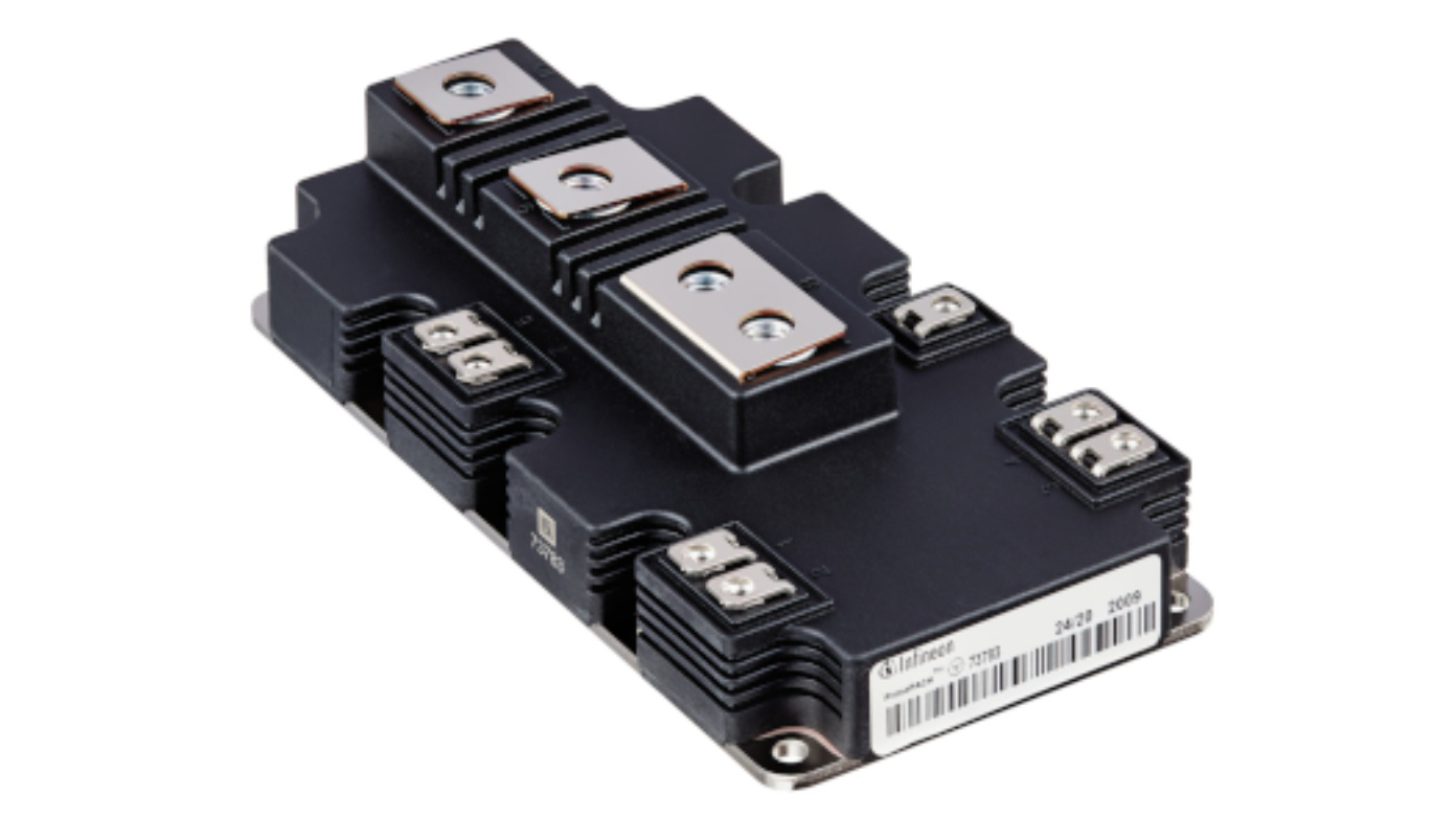
As a flagship product of Infineon, a global leader in power semiconductors, the FF900R12IP4D redefines reliability and efficiency standards for high-power applications through the high-performance DNA of the PrimePACK?2 series. Integrating Trench/Fieldstop IGBT4 technology, an enlarged Emitter Controlled 4 diode, and an NTC thermistor, this module is purpose-built for high-voltage, high-current scenarios, delivering irreplaceable advantages in industrial drives, new energy generation, and traction systems.

As a benchmark of the "Infineon PrimePACK?2" series, the FF900R12IP4D represents not just a technological breakthrough in power electronics, but a core engine propelling industrial automation and the green energy transition. This article will delve into its technical specifications, application scenarios, and selection logic to reveal why it has become engineers’ top choice for high-power designs.
2. Core Product Advantages
In the high-stakes arena of high-voltage, high-current applications, the FF900R12IP4D establishes a technical moat with three core advantages, positioning itself as a "performance benchmark" in industrial and energy sectors. From optimized electrical performance to stable operation in extreme environments and industrial-grade durability, every innovation addresses the core pain points of high-power systems.
2.1 Electrical Performance: Dual Breakthroughs in Efficiency and Stability
As the "central hub" for high-voltage power conversion, the FF900R12IP4D’s electrical parameters are nothing short of versatile:
High-voltage, high-current adaptability: With a collector-emitter voltage (VCES) of 1200V, a continuous DC collector current (Ic nom) of 900A, and a peak current (ICRM) of 1800A, it effortlessly handles high-voltage scenarios like inverters and traction drives, maintaining stability even during short-term current surges. For example, in wind turbine converters, its peak current capability prevents false overload trips during sudden load changes or grid fluctuations, ensuring uninterrupted system operation.
Low loss and high efficiency: Leveraging Trench/Fieldstop IGBT4 technology, its saturation voltage (VCEsat) drops to as low as 1.7V (typical at 25°C) with a positive temperature coefficient—VCEsat increases linearly with temperature. This feature enables automatic current balancing in parallel applications without additional current-sharing circuits, greatly simplifying designs. Combined with low conduction losses and optimized switching characteristics (e.g., a typical turn-on energy Eon of 71mJ), system energy efficiency can be improved by 3%–5%, significantly reducing energy costs for long-running industrial motor drives or photovoltaic inverters.
Robust short-circuit protection: The built-in self-limiting short-circuit current mechanism restricts short-circuit current to 3600A (at 150°C) for ?10μs, buying critical response time for control systems. Unlike traditional IGBTs that rely on external fast fuses, this "self-protection" capability drastically enhances system reliability, especially in safety-critical scenarios like rail transit.
2.2 Thermal Adaptability: Wide-Temperature Operation and Optimized Thermal Management
Temperature stability in harsh environments is the "touchstone" for industrial-grade components:
Wide-temperature stable output: With an operating temperature range of -40°C to 150°C, it covers extreme scenarios from polar wind farms to high-temperature furnaces. Even in desert PV plants (where junction temperatures approach 150°C in summer) or frigid industrial zones in northeast China, the module maintains consistent switching characteristics, avoiding control precision degradation due to temperature drift.
Holistic thermal management:
Internal: The junction-to-case thermal resistance is as low as 29.5 K/kW for the IGBT and 37 K/kW for the diode, ensuring rapid dissipation of power losses and minimizing junction temperature fluctuations.
External: An integrated NTC thermistor (5kΩ nominal resistance at 25°C) enables real-time temperature monitoring. Paired with system-level cooling solutions (such as liquid or air cooling), it achieves thermal runaway ?警 and dynamic power adjustment. In servo systems with frequent motor starts/stops, the NTC provides real-time junction temperature feedback to prevent life degradation from heat accumulation.
2.3 Industrial-Grade Durability
High reliability stems not only from electrical performance but also from "hardcore" mechanical and material design:
Safety compliance: The housing material has a CTI (Comparative Tracking Index) >400, meeting the high creepage requirements of UL 746A. This prevents surface leakage or arcing in high-humidity or dusty environments, adhering to industrial safety standards like EN 61140.
Modular design and maintainability: The PrimePACK?2 package features standardized dimensions with a 33mm creepage distance and 19mm clearance, compatible with mainstream heat sinks and mounting structures. An M5 screw torque range of 3–6N·m, combined with 18nH low-stray-inductance pins, ensures mechanical stability while reducing electromagnetic interference (EMI), cutting system debugging time. Compared to similar modules, maintenance costs are reduced by over 20%.
Long-term durability: Passing over 1000 temperature cycles (-40°C to 150°C), the solder layer and bond wire design resist thermal stress fatigue, extending service life by 15% compared to standard modules. This makes it ideal for hard-to-maintain scenarios like offshore wind farms and mining machinery.
3. In-Depth Technical Specification Analysis
Technical specifications are the "hard metrics" for measuring IGBT module performance. The FF900R12IP4D achieves a golden balance among electrical performance, switching efficiency, and thermal management through precise parameter design. Below, we dissect the underlying logic of its technical advantages starting from core parameters.
3.1 Key Electrical Parameters
| Parameter | Value | Advantage Analysis |
|---|
| Collector-Emitter Voltage (VCES) | 1200V | Adapts to high-voltage systems (e.g., three-phase industrial motor drives, 1000V+ photovoltaic inverters), providing over 20% voltage margin to withstand grid surges and dv/dt spikes. |
| Rated Collector Current (Ic) | 900A (continuous DC)/1800A (1ms peak) | Sustained high-current output meets rated motor load requirements; 1800A peak current handles startup surges (e.g., 2x overload during elevator motor startup), avoiding cost waste from derating designs. |
| Total Power Dissipation (Ptot) | 5.1kW (25°C, Tj=175°C) | Low conduction loss (VCEsat=1.7V typical) and optimized switching loss reduce power consumption by 10% compared to similar 1200V/900A modules, minimizing heat sink size or fan power for compact designs. |
| Gate Threshold Voltage (VGEth) | 5.8V (typical) | Strong noise immunity prevents false triggering from gate noise (recommended drive voltage ±15V), suitable for industrial environments with complex electromagnetic interference. |
The combination of 1200V voltage rating and 900A current rating makes it ideal for 800V high-voltage platforms (e.g., electric vehicle motor controllers), eliminating the need for multi-level series connections to meet voltage requirements and reducing circuit complexity and conduction losses.
The positive temperature coefficient of VCEsat (increases with temperature) creates "natural current balancing" in parallel applications, eliminating the need for additional current-sharing resistors and simplifying PCB layout while enhancing system reliability.
3.2 Switching Characteristics and Loss Analysis
The switching speed and loss of IGBTs directly impact system frequency and temperature rise. The FF900R12IP4D achieves "fast switching, low loss" through structural optimization:
3.3 Thermal Management and Packaging Parameters
Heat dissipation under high power density is key to the module’s long-term reliable operation:
Hardcore thermal material configuration:
Substrate: Oxygen-free copper (Cu) substrate with a thermal conductivity of 401W/(m·K), 5x higher than aluminum substrates, enabling rapid chip heat dissipation.
Insulation layer: Aluminum oxide (Al?O?) ceramic substrate with 4kV RMS isolation voltage, balancing thermal conductivity and electrical isolation to meet EN 60664-1 creepage requirements (33mm creepage distance, 19mm clearance).
Thermal resistance and temperature monitoring:
IGBT junction-to-case thermal resistance (RthJC) 29.5 K/kW, diode 37 K/kW. With a case-to-heatsink thermal resistance of 16 K/kW (using 1W/(m·K) thermal grease), total thermal resistance from junction to heatsink ?70 K/kW at 5.1kW power loss, ensuring junction temperature does not exceed 150°C (safety threshold) when the heatsink is at 85°C.
Integrated NTC thermistor (5kΩ nominal at 25°C, B-value 3375K) supports ±5% accuracy for R100 (100°C resistance), providing real-time junction temperature feedback for thermal simulation and active cooling control.
Packaging reliability details:
Modular design supports double-sided cooling, compatible with liquid-cooled plates or heat pipe heatsinks for different cooling solutions.
Optimized lead resistance (Roc+EE=0.3mΩ) reduces ohmic losses under high current. Combined with 18nH low stray inductance, it mitigates voltage overshoot (ΔV=L×di/dt) during switching, protecting the module and surrounding components.
4. Typical Application Scenarios
4.1 Industrial Drive Applications
High-precision servo motor control (machine tools, robotic arms, automated production lines)
High-power variable frequency drives (driving loads such as fans, pumps, and industrial compressors)
Multi-motor parallel systems (complex ?? scenarios like injection molding machines and printing presses)
4.2 Renewable Energy Applications
Wind power converters (offshore/onshore wind turbines, adaptable to wide-temperature, high-humidity, and salt-fog environments)
Photovoltaic inverters (centralized and string inverters, compatible with 1000V/1500V high-voltage arrays)
Energy storage converters (charge and discharge control for lithium-ion battery and hydrogen energy storage systems)
4.3 Transportation and Power Systems
Electric vehicle traction inverters (motor drives for passenger cars, commercial vehicles, and rail transit)
On-board auxiliary power supplies (high-voltage DC/DC converters, air conditioning compressor control)
Marine electric propulsion systems (variable-frequency drives for yacht and merchant vessel motors)
4.4 Energy and Infrastructure
Uninterruptible Power Supplies (UPS) (backup power for data centers, hospitals, and industrial control)
Grid reactive power compensation devices (high-frequency power conversion for SVG/SVC)
Welding machines and plasma cutting equipment (electric energy control in high-frequency, high-voltage scenarios)
5. Selection Guide: How to Determine if FF900R12IP4D Fits Your Project?
Choosing the right IGBT module for high-power electronic systems requires balancing performance, environment, cost, and reliability. Below, we break down the FF900R12IP4D’s suitability from four core dimensions to help you make quick decisions.
Voltage Considerations
If your system’s operating voltage ?1000V (e.g., three-phase industrial motor drives, photovoltaic inverters), the 1200V collector-emitter voltage (VCES) provides over 20% safety margin to withstand grid surges (e.g., in a 600V system, the module’s voltage rating is twice the nominal voltage for surge protection).
For series applications (e.g., high-voltage energy storage converters), its positive temperature coefficient saturation voltage (VCEsat) simplifies current balancing design, preventing local overheating caused by parameter dispersion in traditional modules.
Current Considerations
Continuous Load: When the motor/inverter rated current ?900A (e.g., drives below 500kW), the module operates stably without derating.
Peak Current Surges: The 1ms peak current (ICRM) of 1800A handles instantaneous overloads like motor startup or short circuits (e.g., 2x current surge during EV motor startup), reducing false protection trips due to insufficient peak current capacity.
Power Density: The compact PrimePACK?2 package is ideal for space-constrained scenarios (e.g., on-board inverters, integrated servo drives), offering 15% higher power density than similar modules at 900A rated current.
Temperature Range
If your project operates between -40°C and 150°C (e.g., outdoor equipment in northern winters, drives near high-temperature furnaces), no additional heating/cooling compensation is needed—direct adaptation is supported.
The integrated NTC thermistor enables real-time junction temperature monitoring, making it suitable for scenarios requiring dynamic power adjustment (e.g., injection molding machines with frequent starts/stops, variable-load operation of wind converters).
Protection and Insulation
The high creepage rating (CTI>400) housing is suitable for high-humidity (e.g., offshore wind), dusty (e.g., mining machinery), or corrosive environments (e.g., chemical production lines), preventing insulation failure due to surface leakage.
A 4kV RMS isolation test voltage and 33mm creepage distance meet industrial safety standards like EN 61140/IEC 60664-1, making it ideal for grid-connected devices with strict insulation requirements (e.g., SVG reactive power compensation devices).
FF900R12IP4D Dimensions
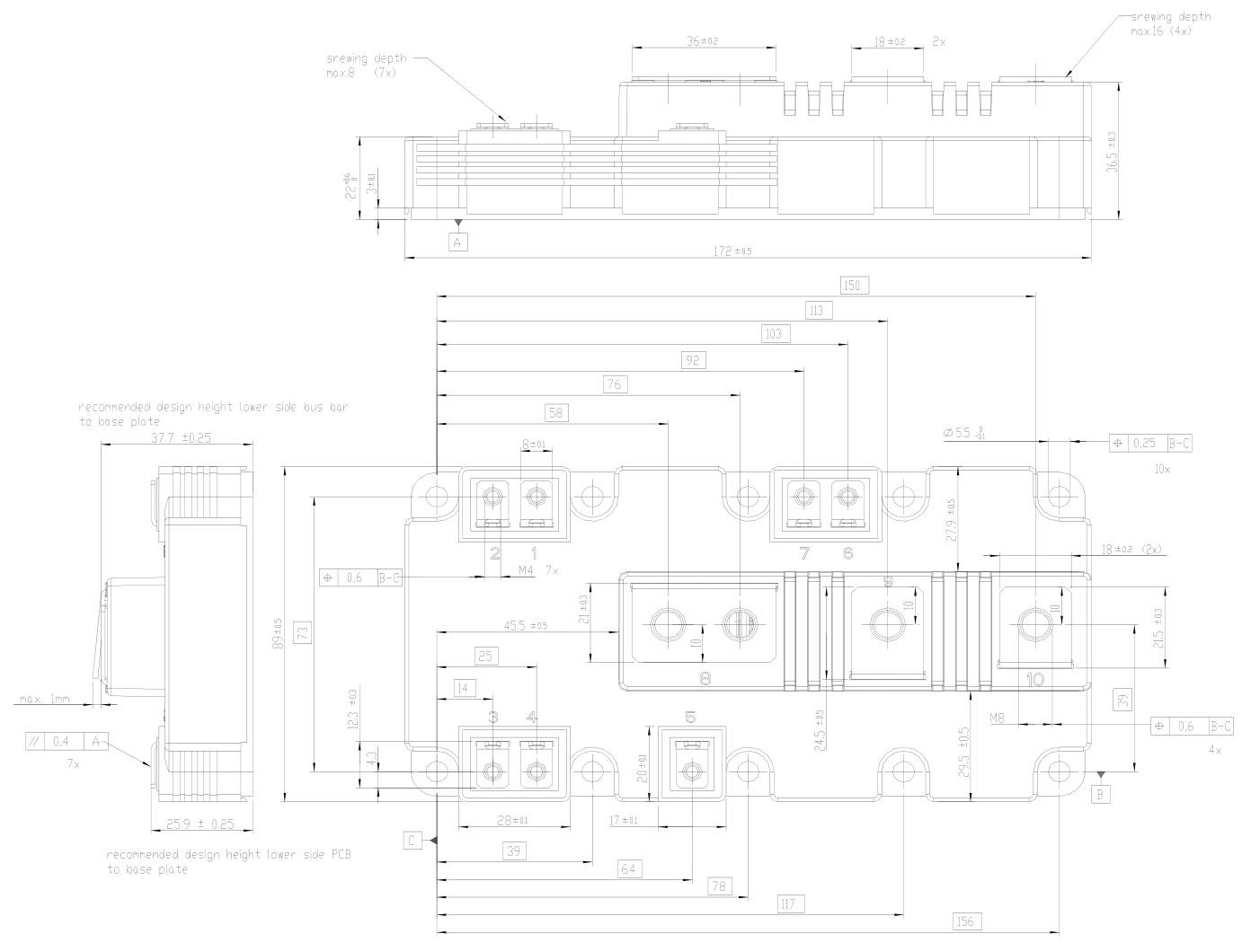
The package outlines of the FF900R12IP4D feature a standardized modular structure, with an overall length of (172 \pm 5) mm. The top view reveals a compact, symmetrical layout with multiple mounting holes (e.g., M4 screw holes) to ensure secure installation. The side view highlights height-related details, such as a recommended lower busbar-to-substrate height of (37.7 \pm 0.25) mm, with heat-dissipating fin structures in certain areas to optimize thermal management. Precise dimensional notations like (36 \pm 0.2) mm and (18 \pm 0.2) mm ensure compatibility with external circuits and heat sinks. The design balances electrical connectivity and mechanical installation norms, providing clear dimensional guidance for integration in real-world applications.

FF900R12IP4D Pin Configuration

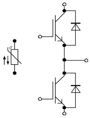
The FF900R12IP4D’s pin configuration is clearly depicted in its circuit diagram, featuring 10 pins with the following functions:
Control Pins: Pins 1 and 4 serve as the gates (G) for the two IGBT units, accepting control signals to enable precise on/off switching of the IGBTs and ensuring efficient, stable power conversion.
Power Transmission Pins: These include collector (C) and emitter (E) pins. Collector pins (e.g., 5, 8) connect to the main circuit’s current input, while emitter pins (e.g., 2, 3) act as current output terminals, collectively handling high-power energy transmission.
Temperature Monitoring Pins: Pins 6 and 7 link to the integrated NTC thermistor, which continuously monitors the module’s temperature and feeds back to the thermal management system for dynamic adjustments. This ensures reliable operation across the wide temperature range of -40°C to 150°C.
Frequently Asked Questions (FAQ)
Does the FF900R12IP4D support high-frequency switching applications?
Yes. The module features optimized switching design with nanosecond-level turn-on/turn-off delay times (e.g., turn-on delay td(on)=0.2μs, turn-off delay td(off)=0.7μs) and low switching losses (Eon=71mJ, Eoff=125mJ). Paired with an efficient diode with reverse recovery charge Qrec=110μC, it operates stably in high-frequency scenarios above 20kHz, such as servo drives and MPPT circuits in photovoltaic inverters.
What are the module’s mounting torque and thermal requirements?
What is the accuracy of the NTC thermistor, and does it support real-time temperature monitoring?
The NTC thermistor has a nominal resistance of 5kΩ at 25°C, a B-value of 3375K, and R100 (resistance at 100°C) accuracy of ±5%, supporting real-time temperature monitoring. Integrated into the module, it provides instant junction temperature feedback for dynamic cooling adjustments or power output control, ensuring stable operation across ?40°C to 150°C.
How does the module’s self-protection mechanism work during short circuits?
The module features a self-limiting short-circuit current design. During a short circuit, current is automatically restricted to 3600A (at 150°C) for ?10μs, buying critical response time for the control system. This internal chip-level mechanism eliminates reliance on external fast fuses, enhancing system robustness in short-circuit scenarios—critical for safety-sensitive applications like rail transit and industrial motor drives.
Reference
Infineon Technologies FF1200R1x PrimePACK?2 Modules
FF900R12IP4D