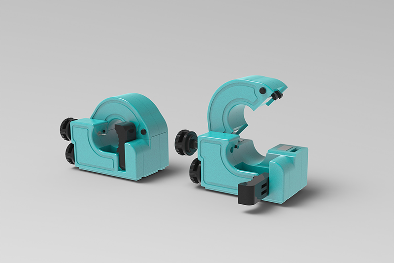
Instrument transformer is a general term for current transformer and voltage transformer. It can change high voltage into low voltage and high current into small current for measurement or protection system. Its function is mainly to convert high voltage or high current into standard low voltage (100V) or standard small current (5A or 1A, both refer to rated value) in proportion, so as to realize the standardization and miniaturization of measuring instruments, protection equipment and automatic control equipment. change. At the same time, the Instrument transformer can also be used to isolate the high-voltage system to ensure the safety of people and equipment.

The use of Instrument transformers
In the power supply line, the current difference is from a few amps to tens of thousands of amps, and the voltage difference is from a few volts to several million volts. The current and voltage in the line are relatively high, such as direct measurement is very dangerous. In order to facilitate the measurement of the secondary instrument, it needs to be converted into a relatively uniform current and voltage, and the Instrument transformer is used to play the role of variable current, variable voltage and electrical isolation.
Most of the display instruments are pointer-type current and voltmeters, so most of the secondary currents of current transformers are ampere-level (such as 5, etc.). With the development of the times, most of the power measurement has reached digitalization, and the signal sampled by the computer is generally in the milliampere level (0-5V, 4-20mA, etc.). The secondary current of the miniature current transformer is milliamp level, which mainly acts as a bridge between the large Instrument transformer and the sampling. Miniature current transformers are called "instrument current transformers". ("Instrument current transformer" has a meaning of multi-current ratio precision current transformer used in the laboratory, which is generally used to expand the measuring range of the instrument.)
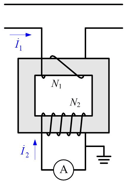
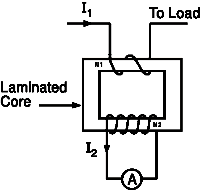
Principle Circuit Diagram of Current Transformer Similar to the transformer, the micro current transformer also works according to the principle of electromagnetic induction. The transformer transforms the voltage while the micro current transformer transforms the current. The winding N1 is connected to the measured current, which is called the primary winding (or primary winding, primary winding); the winding N2 is connected to the measuring instrument, which is called the secondary winding (or secondary winding, secondary winding).

Current transformer principle circuit diagram
The current ratio of the primary winding current I1 of the miniature current transformer to the secondary winding I2 is called the actual current ratio K. The current ratio of the miniature current transformer when it works at the rated operating current is called the rated current ratio of the current transformer, expressed in Kn. Kn=I1n/I2n
Structure principle
There are many different structures of instrument transformer, and we will only introduce the two most important ones below:
1. Structural principle of ordinary current transformer: The structure of current transformer is relatively simple, consisting of mutually insulated primary winding, secondary winding, iron core, frame, shell, terminal blocks, etc. Its working principle is basically the same as that of a instrument transformer. The number of turns (N1) of the primary winding is less, and it is directly connected in series to the power line. When the primary load current (I1) passes through the primary winding, the alternating magnetic flux induction generated produces proportionally reduced Secondary current (I2); the number of turns (N2) of the secondary winding is large, and it forms a closed loop in series with the secondary load (Z) of the current coils such as instruments, relays, and transmitters. Equal ampere turns, I1N1=I2N2, the load impedance of the current transformer is very small in actual operation, and the secondary winding is close to a short-circuit state, which is equivalent to a instrument transformer operating in a short-circuit.

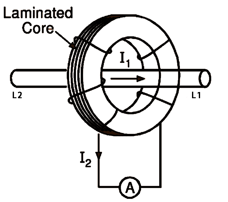
2. The structure of the core-through current transformer does not have a primary winding. The current-carrying (load current) wire from L1 to L2 passes through the circular (or other shape) iron core made of silicon steel sheets to act as a primary winding. The secondary winding is directly and evenly wound on the circular iron core, and is connected in series with the secondary load of the current coils such as instruments, relays, and transmitters to form a closed loop. Since the feedthrough current transformer does not have a primary winding, its transformation ratio is based on the primary The number of turns that the winding passes through the core of the instrument transformer is determined. The more the number of turns through the core, the smaller the transformation ratio; on the contrary, the fewer the number of turns through the core, the larger the transformation ratio, and the rated current ratio I1/n: where I1—— The primary rated current when passing through one turn; n——the number of passing turns.

Main effect
In order to transmit electric energy, the power system often uses AC voltage and high current circuits to send electric power to users, which cannot be directly measured by instruments. The function of the instrument transformer is to reduce the AC voltage and large current proportionally to the value that can be directly measured by the instrument, which is convenient for the instrument to measure directly, and at the same time provide power for the relay protection and automatic devices.
The instrument transformer for power system is a special instrument transformer that transmits the information of high voltage and high current of the power grid to the secondary side of low voltage and small current for metering, measuring instruments, relay protection and automatic devices. The contact element, its primary winding is connected to the power grid, and the secondary winding is connected to the measuring instrument, protection device and so on. Cooperating with measuring instruments and metering devices, transformers can measure the voltage, current and electric energy of the primary system; cooperating with relay protection and automatic devices, they can constitute electrical protection and automatic control of various faults in the power grid. The quality of transformer performance directly affects the accuracy of power system measurement and measurement and the reliability of relay protection device action.
Main categories
Instrument transformer are divided into two categories: voltage transformers and current transformers. Voltage transformers can be used to measure voltage and power in high-voltage and ultra-high-voltage power systems. The current transformer can be used in the measurement of the exchange current, the measurement of the exchange electric degree and the protection in the electric drag line.
1. Voltage transformer:
(1) By use
Measuring voltage transformers or measuring windings of voltage transformers: within the normal voltage range, provide grid voltage information to measuring and metering devices;
Protective voltage transformer or protective winding of voltage transformer: in the state of grid fault, it provides grid fault voltage information to relay protection and other devices.
(2) According to the insulation medium
Dry-type voltage transformer: It is made of ordinary insulating material impregnated with insulating varnish as insulation, and is mostly used at and below low voltage levels;
Pouring insulated voltage transformer: It is molded by casting epoxy resin or other resin mixture materials, mostly used in the voltage level and below;
Oil-immersed voltage transformer: It is insulated by insulating paper and insulating oil. It is the most common structural type in my country, and is often used for voltage levels up to and below;
Gas-insulated voltage transformer: Gas is used as the main insulation, and it is mostly used at higher voltage levels.
The low-voltage transformers usually used for measurement are dry-type, and the high-voltage or ultra-high-voltage sealed gas-insulated (such as sulfur hexafluoride) transformers are also dry-type. The pouring type is suitable for voltage transformers of 35kV and below, and the products above 35kV are oil-immersed.
(3) According to the number of phases
Most of the products are single-phase, because the capacity of the voltage transformer is small, the body is not large, and the internal and external insulation requirements between the three-phase high-voltage bushings are difficult to meet, so only 3-15kV products sometimes use a three-phase structure.
(4) According to the principle of voltage conversion
Electromagnetic voltage transformer: Transform the voltage according to the principle of electromagnetic induction. The principle is completely similar to the basic structure and transformer. It is mostly used at and below the voltage level in my country;
Capacitive voltage transformer: composed of capacitive voltage divider, compensation reactor, intermediate transformer, damper and carrier device protection gap, etc., used for voltage measurement, power measurement, relay protection and carrier communication in neutral point grounding system use;
Photoelectric voltage transformer: through the principle of photoelectric conversion to realize voltage conversion, it is still under development.
(5) According to the conditions of use
Indoor voltage transformer: installed in the indoor power distribution device, generally used at and below the voltage level;
Outdoor type voltage transformer: installed in outdoor power distribution equipment, mostly used at and above the voltage level.
2. Current transformer
(1) By use
Measuring current transformers (or measuring windings of current transformers. Within the normal operating current range, provide current information of the power grid to measuring, metering and other devices;
The current transformer for protection (or the protection winding of the current transformer. In the grid fault state, it provides the grid fault current information to the relay protection and other devices.
(2) According to the insulation medium
Dry-type current transformer: made of ordinary insulating materials treated with dipping paint as insulation;
Casting type current transformer: a current transformer cast with epoxy resin or other resin mixture materials;
Oil-immersed current transformer: Insulated by insulating paper and insulating oil, generally outdoor type. At present, it is commonly used in various voltage levels in our country;
Gas Insulated Current Transformer: The main insulation consists of gas.
(3) According to the principle of current conversion
Electromagnetic current transformer: a current transformer that realizes current transformation according to the principle of electromagnetic induction;
Photoelectric current transformer: A current transformer that realizes current conversion through the principle of photoelectric conversion is still under development.
(4) According to the installation method
Through-type current transformer: a current transformer used to pass through a screen or wall;
Pillar current transformer: a current transformer installed on a plane or a pillar and used as a primary circuit conductor pillar;
Bushing current transformer: a current transformer that is directly set on an insulated bushing without a primary conductor and primary insulation;
Busbar current transformer: a current transformer that has no primary conductor but has primary insulation and is directly set on the busbar.
Development path
Instrument transformer first appeared at the end of the 19th century. With the development of the power industry, the voltage level and accuracy level of instrument transformer have been greatly improved, and many special instrument transformer have been developed, such as voltage and current composite transformers, DC current transformers, and high-accuracy current ratios. And voltage ratiometer, high-current laser current transformer, electronic circuit compensation transformer, photoelectric transformer in ultra-high voltage system, and voltage and current transformer in SF6 fully enclosed combined electrical equipment (GIS). In the power industry, to develop a power system with a voltage level and scale, a instrument transformer with a corresponding voltage level and accuracy must be developed to meet the needs of power system measurement, protection and control.
With the continuous application of many new materials, many new types of instrument transformer have emerged, and electromagnetic transformers have been fully developed. Among them, iron-core current transformers have various structures such as dry type, oil-immersed type, and gas-insulated type. Adapted to the development needs of electric power construction. However, with the continuous increase of power transmission capacity, the continuous improvement of grid voltage level and the continuous improvement of protection requirements, the general iron core current transformer structure has gradually exposed its incompatible weaknesses. Weaknesses such as saturation, ferromagnetic resonance, small dynamic range, and narrow frequency band are difficult to meet the development needs of the new generation of power system automation and power digital network.
With the rapid development of optoelectronic technology, many technologically developed countries have turned their attention to the use of optical sensing technology and electronic methods to develop new electronic current transformers, referred to as photoelectric current transformers. The International Electrotechnical Society has published standards for electronic current transformers. The meaning of electronic transformers includes not only photoelectric transformers, but also various other voltage and current sensors that use electronic testing principles.
Conclusion
Instrument transformers are indispensable components in electrical measurement systems, enabling accurate and reliable monitoring of currents and voltages. Their role in power systems and various industries is paramount for efficient operation and safety. This article has provided an in-depth exploration of instrument transformers, including their types, working principles, applications, and considerations for selection and installation. As advancements in technology continue to shape the field of electrical measurement, instrument transformers will play a crucial role in enabling precise measurements and ensuring the integrity of electrical systems.

Nantian Electronics a professional distributor of electronic components, providing a wide range of electronic products, saving you a lot of time, effort and cost through our meticulous order preparation and fast delivery service.
Share this post


