Thin film and thick film resistors are the most common types on the market. They are characterized by a resistive layer on a ceramic substrate. While they may look very similar, their performance and manufacturing processes are quite different. The nomenclature is derived from the different layer thicknesses. Thin films are about 0.1 microns thick or less, while thick films are about thousands of times thicker. However, the main difference is the method of applying the resistive film to the substrate. Thin film resistors have a metal film vacuum deposited on an insulating substrate. Thick film resistors are manufactured by firing a special paste onto a substrate. The paste is a mixture of glass and metal oxides. Thin films are more accurate, have better temperature coefficients and are more stable. As such, it competes with other technologies with high precision, such as wirewound or bulk metal foil. On the other hand, thick film is preferred because the price is much lower and these high requirements are not important.
What is film resistors
Film resistors, also known as carbon film resistors or metal film resistors, are a type of electronic component used to provide resistance in electronic circuits. They are constructed by depositing a thin film of resistive material onto a ceramic or fiberglass substrate.

The resistive material used in film resistors can be either carbon or metal. Carbon film resistors have a carbon-based resistive layer, while metal film resistors have a thin layer of metal alloy, such as nickel-chromium (NiCr) or tin oxide (SnO2). The resistive film is precisely deposited on the substrate in a spiral or helical pattern, creating a long, thin resistive path.
Advantages of Thin Film Resistors
1. Accuracy: They provide high precision and stable resistance values, making them suitable for applications that require precise resistance values.
2. Low noise: Film resistors have low inherent noise levels, making them ideal for applications where noise interference needs to be minimized.
3. Temperature stability: They exhibit good temperature coefficient characteristics, meaning their resistance value remains relatively stable over a wide range of temperatures.
4. Power handling capability: Film resistors can handle relatively high power levels, making them suitable for a wide range of applications.
Thin film technology
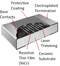
Schematic of a Thin Film Chip Resistor A resistive layer is sputtered (vacuum deposited) onto a ceramic substrate. This produced a uniform metal film about 0.1 microns thick. An alloy of nickel and chromium (nickel) is usually used. They are produced in different layer thicknesses to suit a range of resistance values. This layer is dense and homogeneous, which makes it suitable for trimming the resistance value by subtractive methods. Either by photolithography or by laser trimming, patterns are created to add resistive paths and calibrate the resistance values. The substrate is usually alumina ceramic, silicon or glass. Usually thin films are produced as chip or smd resistors, but thin films can also be applied to cylindrical bases with axial leads. In this context, the term metal film resistor is more commonly used.

Thin films are often used in precision applications. They have relatively high tolerances, low temperature coefficients and low noise. Also for high frequency applications thin films perform better than thick films. Inductance and capacitance are usually low. The parasitic inductance of the thin film can be higher if performed in a cylindrical spiral (metal film resistor). This higher performance comes with cost, which can be a factor above the price of thick film resistors. Typical examples of using thin films are medical equipment, audio equipment, precision control and measurement equipment.
What is film resistors
A thick film resistor is a type of electronic component that is used to provide resistance in electronic circuits. It is constructed by depositing a thick film of resistive material onto a ceramic or glass substrate. The resistive material is typically a mixture of metal oxides, glass, and binders.

The thick film resistor manufacturing process involves screen printing the resistive paste onto the substrate and then firing it at high temperatures to form a stable and durable resistor film. The screen printing process allows for precise control over the dimensions and resistance value of the resistor.
Advantages of Thin Film Resistors
1.Cost-effectiveness: Thick film resistors are generally more cost-effective compared to other types of resistors, such as precision metal film resistors.
2.Wider resistance range: They are available in a wide range of resistance values, making them suitable for various applications.
3.Good temperature stability: Thick film resistors typically exhibit good temperature coefficient characteristics, meaning their resistance value remains relatively stable over a wide range of temperatures.
4.High power handling: They can handle relatively high power levels, making them suitable for applications that require higher power dissipation.
Thick film technology
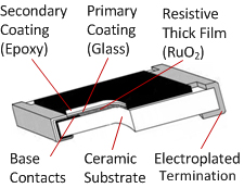
Schematic of a Thick Film Chip Resistor In the 1970s, thick chips became popular. Today, these are by far the most used resistors in electrical and electronic equipment. They are usually available as chip resistors (SMD) and are the lowest cost compared to any other technology.
The resistive material is a special slurry containing a mixture of binder, carrier and metal oxide to be deposited. The binder is a glassy frit, and the carrier is an organic solvent system and a plasticizer. Modern resistive pastes are based on oxides of ruthenium, iridium and rhenium. This is also known as cermet (ceramic-metal). The resistive layer was printed onto the substrate at 850 °C. The substrate is typically 95% alumina ceramic. After firing the paste on the carrier, the film becomes glassy, which makes it well resistant to moisture. The complete firing process is schematically depicted in the figure below. The thickness is about 100 microns. That's about 1000 times more than thin films. Unlike thin films, this process is additive.

The temperature coefficient is typically 50ppm to 200ppm/K. The tolerance is between 1% and 5%. Because of low cost, thicker films are generally preferred where high tolerances, low TCR or high stability are not required. So these resistors can be found in almost any device with an AC plug or battery. The benefits of thick and thin technology are not only lower cost, but also the ability to handle more power, offer a wider range of resistance values and withstand high surge conditions.
Comparing Thin Film and Thick Film Resistors
The main differences between the two technologies are listed in the table below. Components may look the same, but the production methods and electrical characteristics are definitely different.
Thin Film vs Thick Film| Characteristics | Thin Film | Thick Film |
|---|
| Appearance | Thin-film and thick-film chip resistors often have a similar appearance, although the manufacturing process and performance are very different. |
| Film Thickness (μm) | ±0.1 | ±100 |
| Manufacturing Process | Sputtering (Vacuum Deposition) | Screen Printing and Stencil Printing |
| Trimming | Abrasive or laser, for photolithography of complex patterns | A paste of ruthenium oxide or other alloys. |
| Resistive material | A uniform thin film of metal, usually a nickel-chromium alloy | A paste of ruthenium oxide or other alloys. |
| Resistance value (Ω) | 0.2 - 20M | 1 - 100M |
| Tolerance (%) | ±0.1 - ±2 | ±1 - ±5 |
| Temperature Coefficient (ppm/K) | ±5 - ±50 | ±50 - ±200 |
| Maximum operating temperature (°C) | 155 | 155 |
| Maximum working voltage Umax (V) | 50 - 500 | 50 - 200 |
| Nonlinearity (dB) | > 110 | > 50 |
| Current noise (μV/V) | <0.1 | <10 |
| Rated power P 70 (W) | 1/16 - 1 | 1/16 - 1/4 |
| Stability of P 70 (1000h) ΔR/R% | ±0.15 - ±0.5 | ±1 - ±3 |
| Moisture Resistance | Thick films are more resistant to moisture because they are like glass. |
| High Frequency Behavior | Thin films have low parasitic inductance and capacitance. However, if the thin film is performed in a helically cut cylindrical shape, the inductance can be high. |
| Typical areas of use | High precision: measurement or monitoring equipment, medical or audio applications, precision control. | Very wide for almost any electrical device with a battery or AC connection. A common PC contains over 1000 thick film and thin film resistors. |
| Cost | More expensive than thick film. | The lowest priced resistor type on the market. Preferred solution if performance requirements are low |

Nantian Electronics a professional distributor of electronic components, providing a wide range of electronic products, saving you a lot of time, effort and cost through our meticulous order preparation and fast delivery service.
Share this post


