IGBT is the most mature and widely used power device among high-power switching components at present. It has low driving power and low saturation voltage, and is the core device for energy conversion and transmission.

 保 存
保 存


What is IGBT?
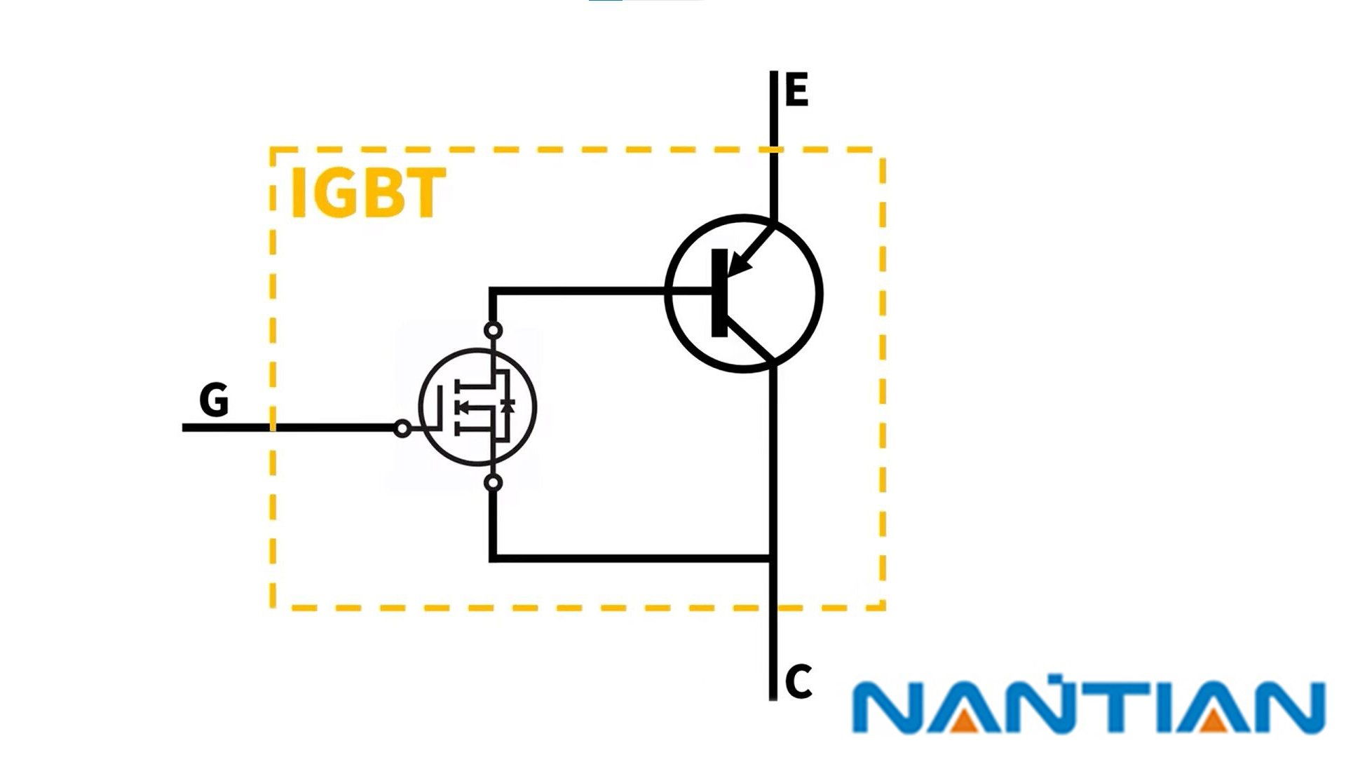
IGBT (Insulated Gate Bipolar Transistor), an insulated gate bipolar transistor, is a composite fully-controlled voltage-driven power semiconductor device composed of a bipolar transistor and an insulated gate field effect transistor, and has a metal oxide half field effect transistor. The advantages of both high input impedance and low turn-on voltage drop of the power transistor. The saturation voltage of GTR is low, the carrying current density is large, but the driving current is large; the driving power of MOSFET is small, the switching speed is fast, but the conduction voltage drop is large, and the current carrying density is small. The IGBT combines the advantages of the above two devices, with low driving power and low saturation voltage. It is very suitable for the conversion system with a DC voltage of 600V and above, such as AC motors, frequency converters, switching power supplies, lighting circuits, traction drives, etc.
IGBT is the core device of energy conversion and transmission, commonly known as the "CPU" of power electronic devices, and is widely used in rail transit, smart grid, aerospace, electric vehicles and new energy equipment.
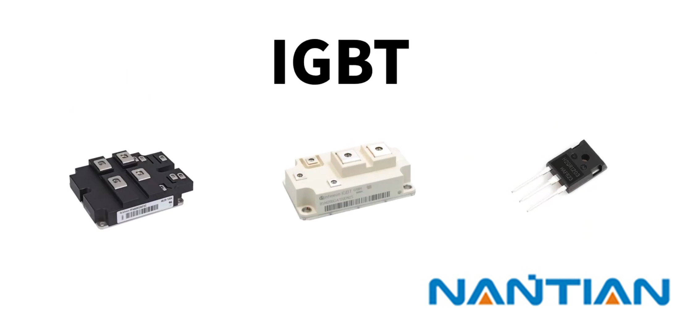
The IGBT module is a modular semiconductor product that is packaged by IGBT (insulated gate bipolar transistor chip) and FWD (freewheeling diode chip) through a specific circuit bridge; the packaged IGBT module is directly applied to inverters, UPS uninterrupted power supply and other equipment.
Structure of IGBT
An Insulated Gate Bipolar Transistor (IGBT) is a three-terminal semiconductor device that has high input impedance like a MOSFET and low output impedance like a BJT (Bipolar Junction Transistor). It's essentially a combination of these two devices, with a structure that supports both high voltage and high current applications.
Here is a breakdown of the IGBT structure:
Collector: This is the region through which the current exits the device. In an NPN-based IGBT (the most common type), the collector is typically composed of n+ type silicon. The n+ designation indicates a high concentration of free electrons.
Drift Region (n- layer): Located just above the collector, this lightly doped n-type silicon layer (n-) drift region is responsible for supporting the high blocking voltage of the IGBT. The thickness and doping level of the drift region determines the device's breakdown voltage.
P-base Region: This layer, made of p-type silicon, forms a p-n junction with the drift region. When a positive voltage is applied to the gate, it modulates the conductivity of this p-n junction.
Emitter: The emitter is the terminal through which the current enters the device. In an NPN-based IGBT, the emitter is composed of p+ type silicon. This creates a second p-n junction between the p-base region and the emitter.
Gate: The gate is composed of a thin layer of silicon dioxide (SiO2), which is insulating, overlaid with a layer of polycrystalline silicon. This structure forms a MOS (Metal-Oxide-Semiconductor) capacitor. When a voltage is applied to the gate terminal, it influences the conductivity of the p-base region, enabling control over the device's operation.
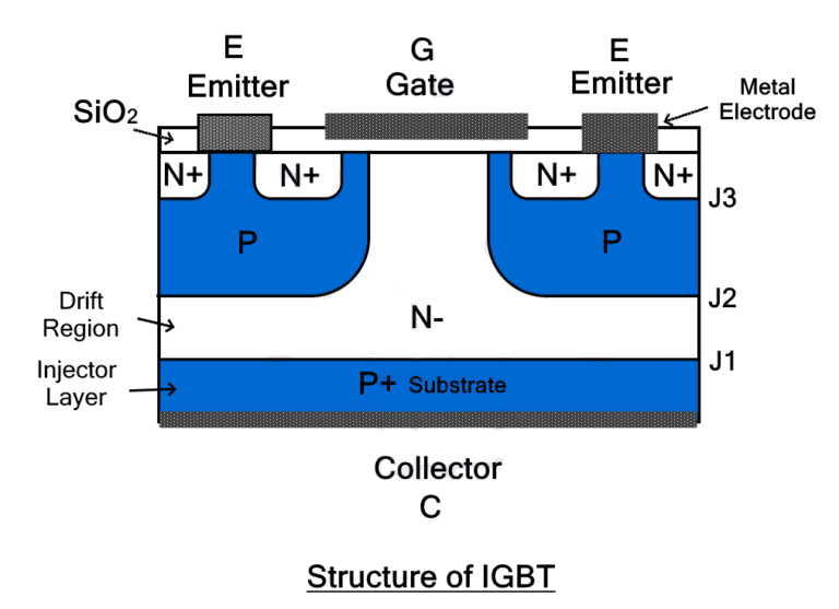
The IGBT consists of four layers of semiconductors to form a PNPN structure. The collector (C) is connected to the P layer, and the emitter (E) is connected between the P and N layers. P+ substrates are used to build IGBTs. N layer is placed on it to form PN junction J1. Two P regions are fabricated on top of the N layer to form a PN junction J2. The P region is designed in such a way that there is a path in the middle for the gate (G) electrode. As shown, the N+ region diffuses into the P region.
This layered structure of alternating p-type and n-type silicon creates two p-n junctions, similar to a BJT, while the gate structure shares similarities with a MOSFET. This hybrid structure allows the IGBT to combine the benefits of high input impedance (due to the insulated gate) and low conduction losses (thanks to the bipolar action), making it ideal for many power electronics applications.
Application of IGBT
The Insulated Gate Bipolar Transistor (IGBT) has become a pivotal component in numerous electronic systems due to its unique blend of high efficiency, fast switching, and substantial power handling capabilities. Here are some of the key applications of IGBT:
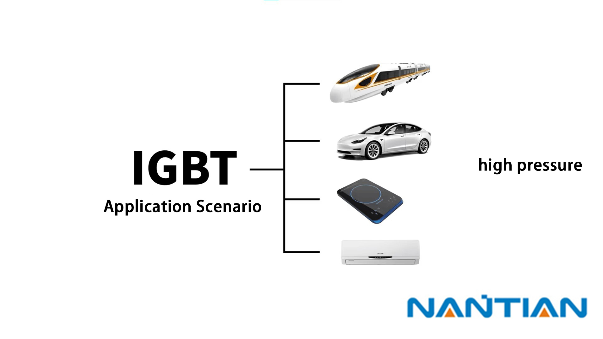
Renewable Energy Systems: In both wind and solar power generation systems, IGBTs are used extensively in inverters to convert direct current (DC) produced by solar panels and wind turbines into alternating current (AC) that can be fed into the power grid or used directly by AC equipment.
Electric Vehicles (EVs) and Hybrid Electric Vehicles (HEVs): IGBTs are fundamental in the power electronics of EVs and HEVs. They are used in the inverter units that drive the electric motor and in the converters that manage the battery charging and discharging process.
High-Speed Trains: IGBTs are used in the traction inverters of high-speed trains, converting the DC power from the overhead lines into AC for the train's traction motors.
Uninterruptible Power Supplies (UPS): IGBTs are used in the inverters of UPS systems to ensure a continuous, clean AC power supply even when the main power source fails. The IGBTs allow for a rapid switch from the main power source to the battery backup.
Switch-Mode Power Supplies (SMPS): IGBTs are used in SMPS to improve efficiency, reduce heat, and provide rapid switching capabilities. SMPS are commonly used in computer power supplies and other electronics that require stable DC voltage.
Induction Heating: IGBTs are extensively used in induction heating systems due to their high-frequency operation, contributing to the system's overall efficiency and effectiveness. 7. **Audio Amplifiers:** Class D audio amplifiers use IGBTs for their high-speed switching capabilities, leading to higher efficiency and smaller sizes compared to traditional amplifier designs.
The difference between IGBT and MOSFET and Triode
In our circuit, it is often necessary to use high-speed switches to generate PWM waves. This switch can be MOS(Metal Oxide Semiconductor), triode or IGBT. There are generally three dimensions of which tube to choose: current, withstand voltage, frequency, But none of the three of them can meet these three conditions at the same time. The short board of MOS is voltage resistance, so it can only exist in low-voltage scenarios. The short board of the triode is the current and switching frequency; the short board of the igbt is the switching frequency. So we need to choose different components according to different application
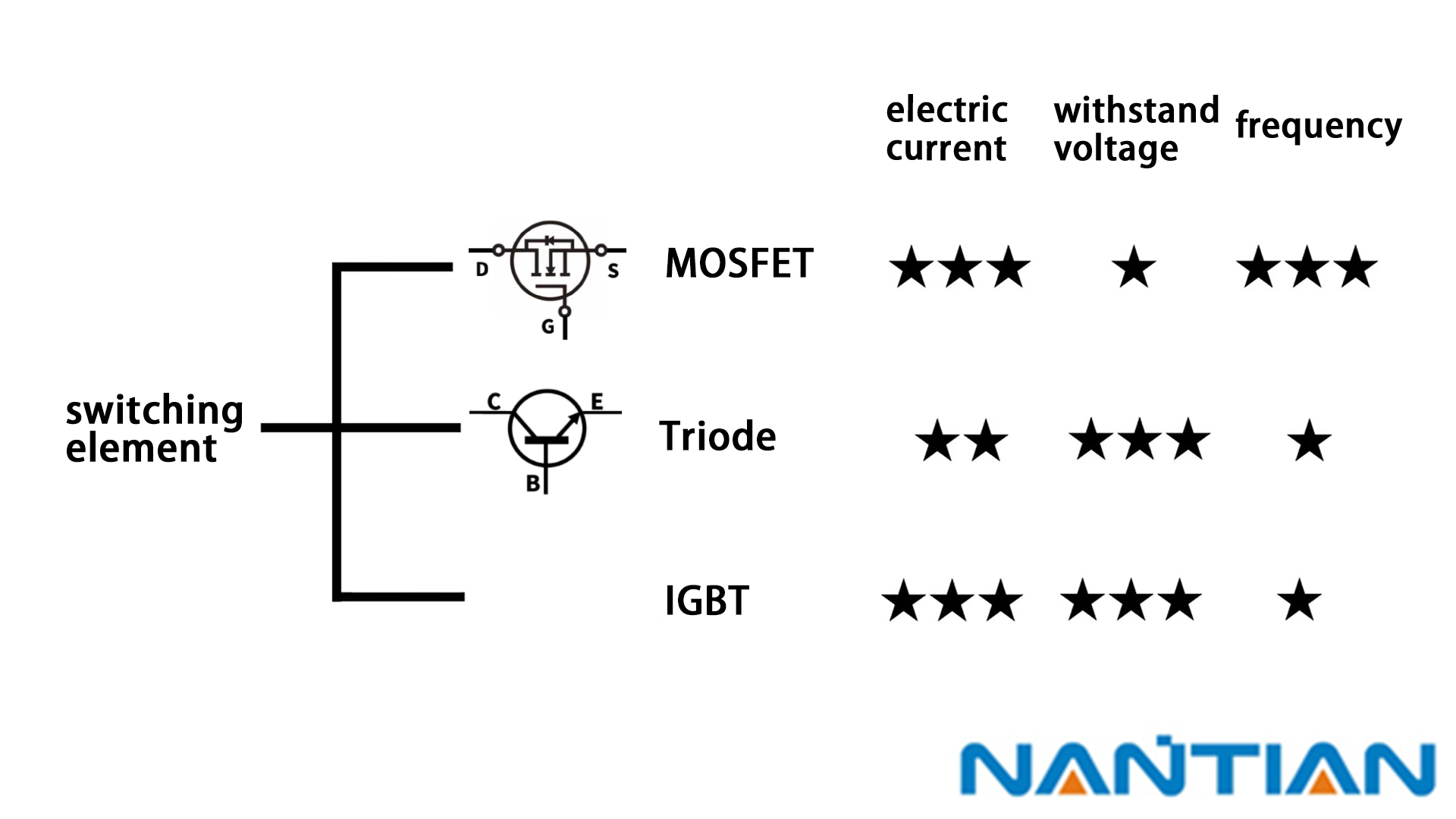
For MOS, its biggest problem is that it cannot withstand high voltage, and the general limit is 400 volts, so it is not suitable to use MOS tubes (low MOS withstand voltage) in high-speed rail, electric vehicles, and induction cooker scenes where the power supply voltage is relatively high. It is easy to be burned, so are there any components that can withstand high voltage? The answer is the triode. The CE withstand voltage of the triode can be made very high, which can reach thousands of volts. Can the triode be used in electric vehicles? The answer is no. Although the triode has a high withstand voltage, electric vehicles require a lot of current. If only one triode is used, a driving power supply is needed, so only one triode is not enough.
If we use the triode and MOS together, we can withstand high voltage and high current at the same time. This combination of triode and MOS is a simple IGBT!
